A 7.5 mm espag specification normally describes the square spindle, while 19 mm describes the backset from the gearbox faceplate to the spindle axis; they are separate measurements, not two versions of the same lock. By checking the existing mechanism, profile, locking-point layout and frame keeps, you can identify a compatible replacement before ordering or installing it.
Key takeaways
- Measure the spindle centre and backset before ordering a replacement.
- Match the gearbox to the window profile and existing locking points.
- Check corrosion, dust and humidity exposure at the Mumbai installation site.
- Specify dimensions, rod length, locking points and keep positions in writing.
What 7.5 mm and 19 mm mean in an espag lock
The 7.5 mm and 19 mm figures describe different parts of an espag locking system. The 7.5 mm figure identifies the square spindle that passes from the handle into the central gearbox. The 19 mm figure identifies the backset: the distance from the gearbox faceplate or front edge to the spindle’s centre axis.
They are not interchangeable versions of one measurement.
| Dimension | Part identified | What it controls |
|---|---|---|
| 7.5 mm square spindle | Handle spindle and gearbox socket | The fit between handle and gearbox, and the amount of cam rotation |
| 19 mm backset | Gearbox faceplate to spindle centre | The handle’s position relative to the sash edge and the window profile |
Turning the handle rotates the spindle inside the gearbox. The gearbox transfers that rotation through drive rods to corner drives, shootbolts, rollers or mushroom cams, which enter frame keeps around the sash. The keeps provide the fixed resistance that pulls the sash closed and maintains compression against the gasket.
Do not substitute a nominal 7 mm handle or gearbox for a 7.5 mm spindle. The clearance can create handle play, incomplete locking-point movement and accelerated wear, even when the faceplate and screw holes align.
A replacement espagnolette lock must also match the rods, cam geometry and keeps; matching only the spindle and 19 mm backset does not prove system compatibility.
How to measure the existing window lock before ordering
Measure the existing mechanism before removing it, because a matching 7.5 mm spindle alone does not prove compatibility. Use a vernier calliper to measure the spindle across its square flats, not diagonally; record the spindle projection from the handle rose or gearbox, plus the handle fixing-hole centres.
- Handle: record the spindle size, projection, fixing-hole spacing, handle orientation, brand mark and any model code.
- Gearbox: measure height, width and depth; record the spindle-axis position, 19 mm backset, latch or cam height, screw centres, handing marks and stamped identification.
- Faceplate: record its full length, faceplate width, screw-hole spacing, end shape and any stamped brand or profile code.
- Rods: measure each rod from the gearbox connection to its end, then record the rod cross-section, connector shape, adjustment slots and the distance from the handle centre to the nearest locking point.
- Locking points: count every mushroom cam, shootbolt or roller and note each centre-to-centre position along the sash.
| Measurement | Record | Why it matters |
|---|---|---|
| Spindle | 7.5 mm square and projection | A 7 mm part can leave play and incomplete rotation |
| Backset | Faceplate edge to spindle axis | Confirms the 19 mm gearbox geometry |
| Gearbox | Height, width, depth and screw centres | Prevents profile fouling and mounting mismatch |
| Faceplate | Width, length and fixing pattern | A different width can expose or obstruct the channel |
Keep the removed gearbox and rods, or make a dimensioned drawing. Send both to the supplier and request a pre-dispatch compatibility check; photographs often hide cam height, faceplate width and the rod-end interface.
Check profile, locking points and Mumbai site conditions
Confirm the fit with a physical match, not the nominal dimensions alone. A 7.5 mm spindle and 19 mm backset identify the handle spindle and sash-edge-to-spindle-centre distance; they do not confirm the gearbox case, faceplate, Euro-groove or frame keeps.
Keep the removed mechanism or a dimensioned drawing beside the supplier’s drawing and compare:
- Profile: match the aluminium window fittings or UPVC window hardware channel, Euro-groove dimensions, faceplate width, gearbox depth and clearance around the sash.
- Gearbox: check spindle position, cam height, fixing-hole pattern, handing, reversibility and the rod-end connection. Two 19 mm gearboxes can have incompatible bodies.
- Locking points: mark every cam, roller or mushroom bolt on the sash, then measure its pitch and height against each frame keep. The replacement must place every point directly opposite its keep.
- Assembly: verify rail length, corner drives, extensions and rod compatibility. A central gearbox will not correct different rod-end geometry or locking-point spacing.
- Site conditions: check sash height, opening direction, concealed or surface-mounted routing, and whether coastal salt, dust, swollen seals or sash drop has shifted the keeps.
Before dispatch, send the sample and photographs showing the full faceplate, rods and keeps, but rely on the sample or drawing for approval. Ask for a written compatibility check. Test with the handle removed first: the rods must travel freely, and the sash must close without lifting or forcing before final handle fitting.
Install the gearbox, rods and keeps without forcing the handle
Install the gearbox first, connect the drive rods and corner drives, then position the keeps against the actual locking points; never use the handle to pull a misaligned sash into place.
1. Remove the handle and record its orientation. Remove the sash if access to the full mechanism is restricted, supporting it so the hinges and frame are not loaded.
2. Take out the old faceplate, gearbox, drive rods and corner drives. Keep the screws only if they are undamaged and long enough to enter sound frame material.
3. Set every adjustment cam to its neutral position. Fit the replacement gearbox with its spindle centre aligned to the existing handle holes, then secure it lightly so it can still move during alignment.
4. Insert the drive rods into the gearbox and connect each corner drive or extension. Confirm that every mushroom cam moves freely and follows the same travel as the original mechanism before tightening the faceplate screws.
5. Operate the handle with the sash open. It must rotate smoothly through the complete locking and unlocking movement; stop if it binds, stops short or develops play.
6. Close the sash gently and mark where each mushroom cam meets its frame keep. Fix or reposition the keeps so the cams enter centrally without striking their edges.
7. Check the gasket compression and sash alignment, then tighten the gearbox, faceplate and keep screws. A stiff handle indicates misalignment, not a need for more force. Adjust hinges, keeps or cams until the handle closes without resistance.
What to put in the purchase specification for a Mumbai replacement
Require a written system specification, not just “7.5 mm spindle, 19 mm backset.” Send the supplier a physical gearbox sample or a dimensioned drawing and request a pre-dispatch compatibility check; photographs often conceal cam height, faceplate width and the rod-end interface.
| Nominal listing | Complete purchase requirement | Why it matters |
|---|---|---|
| 7.5 mm / 19 mm | Spindle measurement, backset reference and spindle projection | Confirms the handle reaches the gearbox correctly |
| Gearbox only | Rail length, faceplate width, thickness, finish and screw centres | Prevents clashes with the sash profile |
| “Multipoint” | Locking-point layout, point count, cam type and cam height | Every cam or bolt must meet its frame keep |
| Universal | Handing, reversibility, rod compatibility and opening direction | A handed gearbox can be unusable on the opposite sash |
| Standard hardware | Fixing-screw size, handle fixing-hole spacing and handle inclusion | Avoids missing parts or unsuitable screws |
Add the window profile and hardware channel: aluminium or uPVC, Euro-groove or another routing, concealed or surface-mounted drive, sash height and opening direction. State the existing brand or gearbox pattern if marked.
For Mumbai, specify corrosion resistance as a system requirement. Ask whether exposed components are 316 stainless steel, identify any zinc-plated steel, and request salt-spray or corrosion-test documentation. Also confirm drainage paths, coating quality and isolation between dissimilar metals.
If Aruna Techno Industries is quoting, give it the same sample, drawing and locking-point layout rather than asking it to match nominal dimensions. The quotation should name the inspection responsible for the compatibility check.
Related product
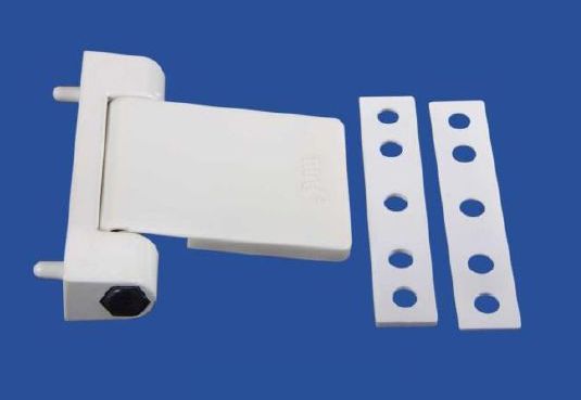 | UPVC Window & Door Hardware UPVC Dooe Hardware View product → |
Frequently asked questions
What do 7.5 mm and 19 mm mean in an espag lock?
The 7.5 mm figure identifies the square spindle entering the gearbox. The 19 mm figure is the backset from the gearbox faceplate to the spindle centre.
How do you measure an existing espag window lock?
Measure the spindle size, backset, faceplate dimensions, rod length and each locking-point position before ordering.
What should you check before replacing an espag lock in Mumbai?
Check the window profile, the number and position of locking points, and exposure to humidity, dust and corrosion.
How should you install the gearbox, rods and keeps?
Align the gearbox and rods with the existing profile, position each keep accurately and test the handle without forcing it.
What belongs in a Mumbai espag lock purchase specification?
State the spindle size, 19 mm backset, faceplate, rod length, locking-point layout, profile, handing and site conditions.